How to Cut a Birdsmouth Joint for Roof Rafters
A birdsmouth joint lets a sloping roof rafter sit flat on a wall plate or beam. This guide shows you how to mark the notch, check its depth and cut it cleanly, with diagrams and a worked example in metric and imperial measurements.
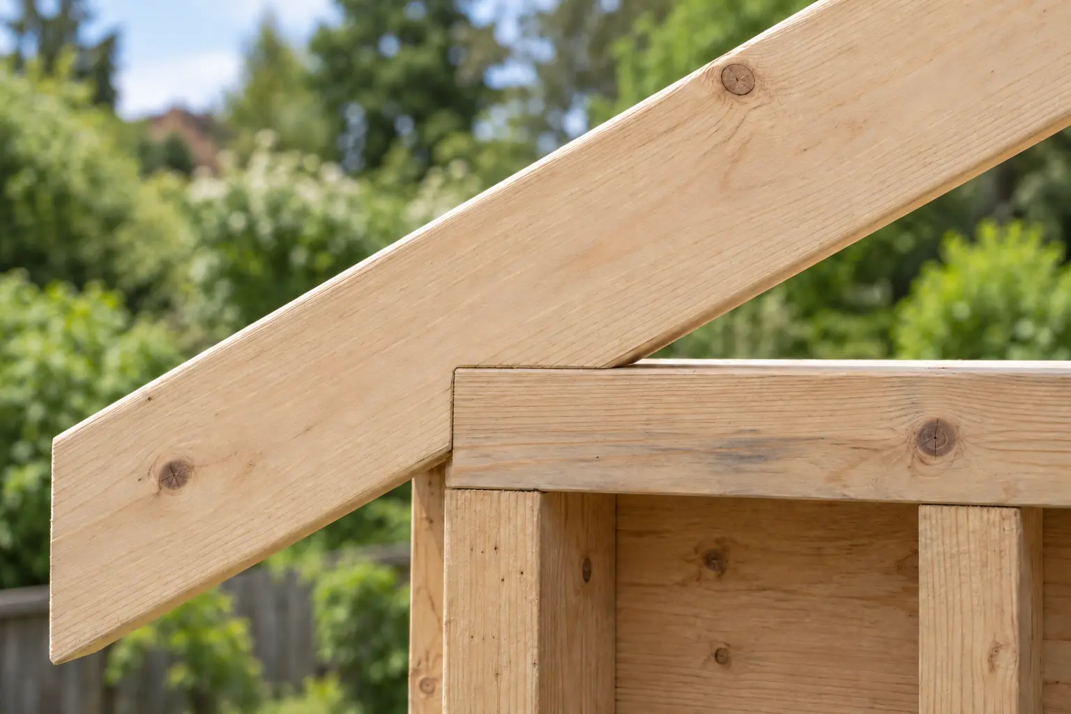
What is a birdsmouth joint?
A birdsmouth joint is a notch in the underside of a sloping roof rafter. Its horizontal seat cut rests on a wall plate or beam, while its vertical heel cut meets the support’s side. The notch provides a flat bearing surface.
The seat and heel
Tools for cutting a birdsmouth
- Specified structural timber, checked for significant bow, twist, splits and defects around the notch
- Tape measure, sharp pencil and a framing square or rafter square
- Level for the trial fit
- Handsaw, or a circular saw plus a handsaw to finish the corner
- Stable trestles, clamps, eye and hearing protection, and suitable dust protection
Work at a comfortable height with the rafter clamped securely. Support the timber so the cut cannot close on the blade. Disconnect power before adjusting the saw.
Use the birdsmouth layout calculator to calculate the heel, perpendicular notch depth and height above plate from your specified dimensions
Worked example: a 2×8 rafter at 6:12
This example uses a 2×8 rafter at a 6:12 pitch on a 2×4 wall plate. The actual rafter depth is 7¼ in (184.2 mm), and the plate is 3½ in (88.9 mm) wide. A 6:12 pitch rises 6 units for every 12 units of horizontal run, giving an angle of about 26.6°.
| Measurement | Imperial | Metric |
|---|---|---|
| Seat length | 3½ in | 88.9 mm |
| Vertical heel | 1¾ in | 44.5 mm |
| Perpendicular notch depth | About 1.57 in | 39.8 mm |
| Height above plate (HAP) | About 6.36 in | 161.4 mm |
Metric values convert the actual imperial stock sizes. Calculated values are rounded; use the plan’s dimensions for cutting. This example does not establish a suitable rafter span or load capacity.
Before starting the roof, resolve the shed foundation and fastener specification. For an enclosed store, also plan how to manage condensation.
Plans for your next build
Choose your project, then follow its specified roof and connection details.
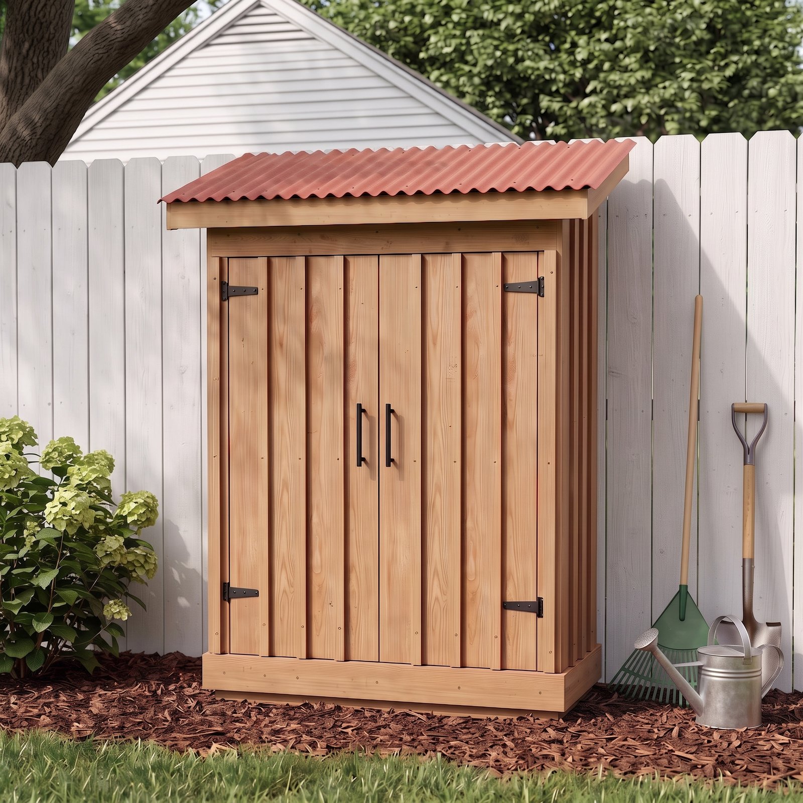
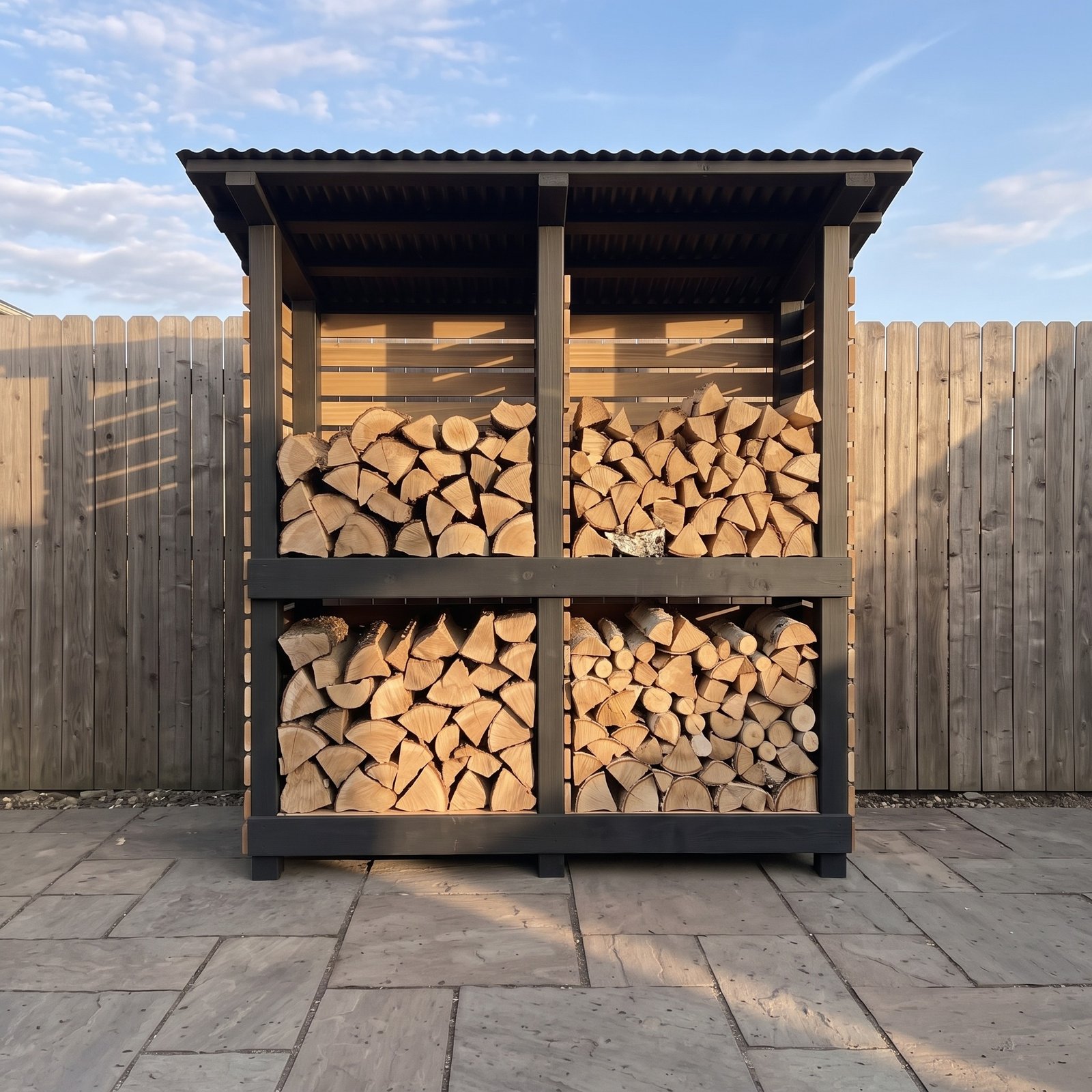
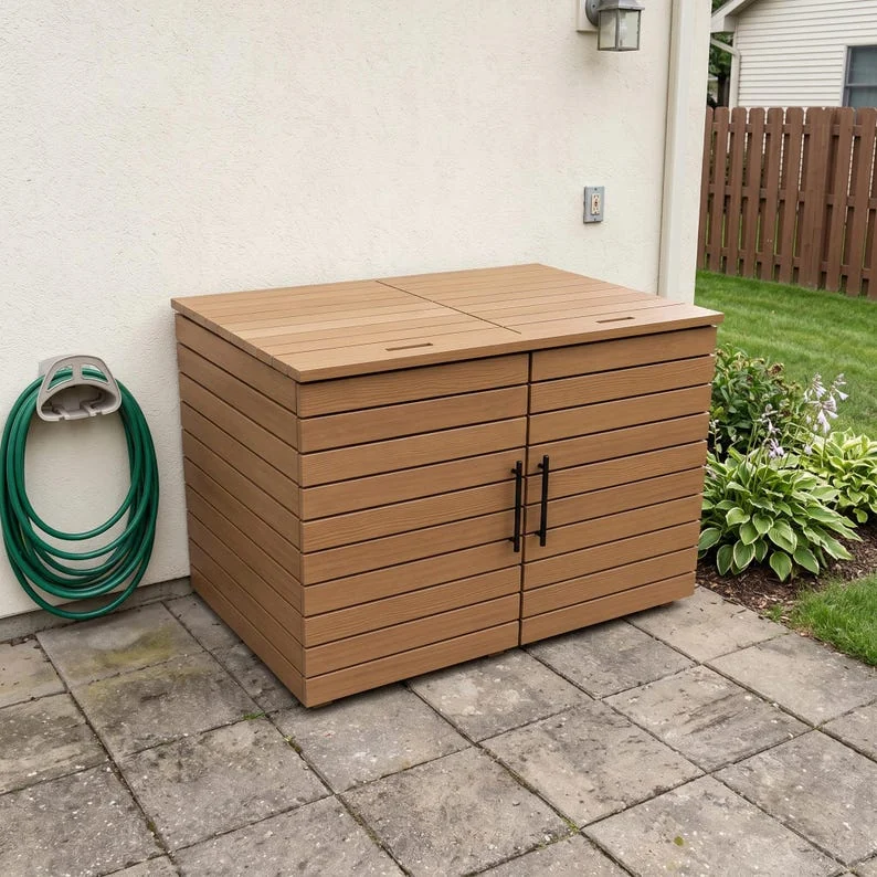
1. Choose a pattern rafter and locate the heel
Sight along the timber and identify any slight crown, the upward curve along its length. Mark the top edge so that the crown faces up when installed. Set aside badly bowed, twisted or split pieces, and choose a straight, sound piece for the pattern.
Mark the ridge end and tail end. Locate the heel using the drawing’s stated reference point and measurement direction. A horizontal run is not the same as a distance along the rafter. If the dimension runs from a finished ridge cut, follow that reference and any ridge-thickness allowance exactly.
Check the actual support positions and levels before cutting.
2. Mark the heel and seat cuts
For the 6:12 example, place a framing square flat on the rafter’s broad face. Keep 6 on the short leg and 12 on the long leg against the same lower edge. Stair gauges can help repeat that setting. Position the short leg through your heel-location mark and draw the heel line.
The heel line will be vertical when installed. If you use a rafter square instead, use its common-rafter pitch scale: 6:12 is not 6°.
Use the top edge as your reference
Height above plate (HAP) is the distance along the heel line from the top of the support to the top edge of the rafter. Starting at the top edge, measure down the heel line by the specified HAP and mark the seat corner.
Our example gives a HAP of about 6.36 in (161.4 mm). Lay out the specified seat length and pitch, or use the plan’s dimensioned HAP.
Consistent HAP aligns the rafter tops when support levels and pitch match. If board depths vary, check the notch depth on each piece.
Draw the seat through that mark
Keep the square at the same 6 and 12 setting and slide it along the lower edge until its long leg crosses the HAP mark. Draw along that leg to the lower edge. The seat and heel lines meet at 90°.
Mark the small triangle as waste. Transfer the lines onto the other broad face and connect them across the narrow edge so you can check both sides while cutting.
Height above plate
Use the square to mark both cuts
3. Check bearing and notch depth
Check that the seat provides enough bearing and the notch leaves enough timber. A short seat reduces bearing; a deep notch weakens the rafter.
The allowable birdsmouth depth depends on the material, local code and support detail. A one-quarter-depth limit applies to certain solid-sawn end notches; cantilevered-rafter provisions can differ. Do not treat either one-quarter or one-third as universal. IRC cutting and notching provisions
Measure rafter depth using the actual timber size, perpendicular to its long edges. Measure notch depth in the same direction, rather than vertically along the heel.
Measure across the timber
Check the example before cutting
The notch depth is seat length × sin(roof angle). Our 3½ in seat at 26.6° removes about 1.57 in (39.8 mm), measured perpendicular to the rafter edge.
If the applicable detail limits the notch to one-quarter of the actual depth, the limit for this 7¼ in rafter is 1¹³⁄₁₆ in (46.0 mm). This example falls within that geometric limit. That check alone does not establish the rafter’s span or load capacity.
The 2021 IRC gives a baseline end-bearing requirement of 1½ in (38 mm) on wood or metal, with other provisions for different supports and connections. The project may require more bearing. IRC bearing requirements
Before cutting, keep the seat within the supported width and check that it provides the required bearing. If bearing and notch-depth requirements conflict, resolve the roof detail. Once an oversized notch has been cut, removing more timber cannot restore it.
4. Cut out the waste
Clamp the rafter with the marked face visible. For a simple birdsmouth, the saw cuts square through the timber’s thickness; the pitch is in the layout lines on the broad face. Check the blade’s bevel setting before cutting. Set the blade depth for the timber’s thickness according to your saw manual, rather than using full depth by default.
- Cut along the heel line from the lower edge toward the inside corner, keeping the saw kerf (the slot removed by the blade) on the waste side of the line.
- Cut along the seat line from its intersection with the lower edge toward the same corner.
- Stop the circular saw short on both faces. Its curved blade can extend beyond the corner on the hidden face before the visible cut looks complete.
- Finish with a handsaw. Remove the triangular waste and trim only the small high spots needed to reach your lines.
You can also make both cuts entirely with a handsaw.
A clean corner, without extra kerfs
5. Test-fit the first rafter
Put the sample rafter in its intended position using safe access and temporary support. Do not leave it unsecured overhead.
- The seat contacts the support evenly without rocking
- The heel aligns with the intended face of the plate or beam
- The top end or opposite bearing fits at the planned roof pitch
- The overhang matches the drawing
- The notch stays within the specified limits and the corner has no overcut or split
If it rocks, check for a small uncut nib, a cut out of square through the thickness, or an uneven support. If the angles or location are wrong, recheck the layout. Do not pull a poor fit into place with screws or keep removing timber until it drops.
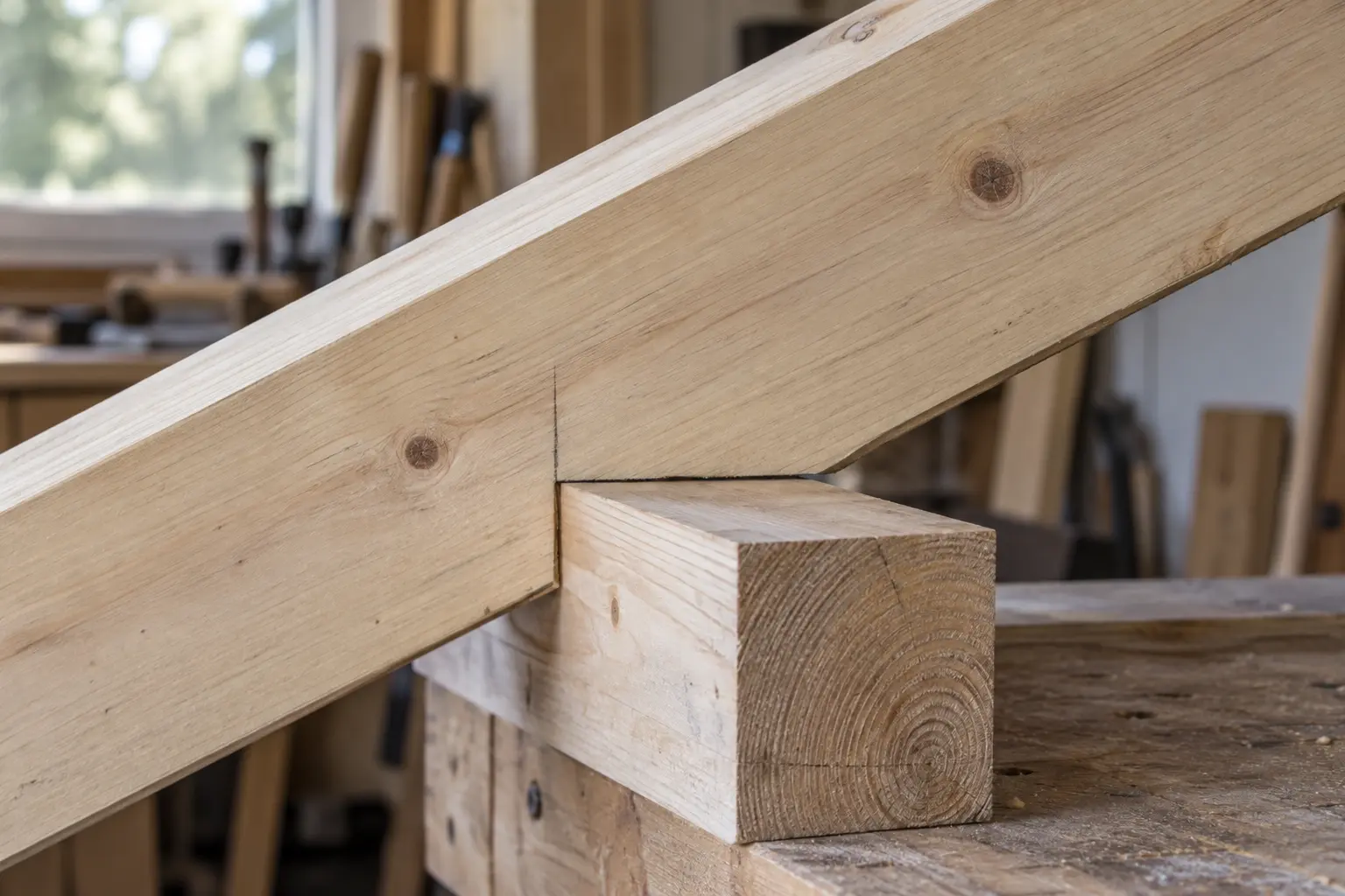
6. Copy the checked rafter and install
Once the first rafter fits, mark it MASTER. Use that same piece for each matching rafter, aligning the same top edge and end reference every time. Copying each new rafter from the last can gradually shift the layout.
Only use the template where the roof geometry and support positions are identical. Check for changes in timber depth, wall level or span before cutting a batch.
The birdsmouth provides bearing, not uplift restraint. Install the specified fixings, blocking and bracing. Where a connector is required, use the exact fastener type, size and quantity listed for that connector. Ordinary deck screws are not an automatic substitute for connector nails or approved structural screws. Manufacturer’s connection specifications
For preservative-treated timber, follow the treatment supplier’s instructions for exposed cuts and compatible metalwork.
What changes on a shed or lean-to roof?
Sloped roof joists can use the same birdsmouth principle as rafters. Horizontal ceiling and floor joists already have level undersides and do not normally need this notch.
In the two-notch detail shown below, the low-wall heel sits at the outside wall face and the high-wall heel at the inside face. Identical notches work only when the support widths, levels, pitch and specified bearing detail allow them. Some roofs use hangers or other connections instead.
For matching notches on a straight member, convert the horizontal distance between the two heel faces into a sloping distance using horizontal distance × √(1 + (rise/run)²). At 6:12, a 48 in horizontal distance becomes about 53.67 in along the rafter. A 1,200 mm horizontal distance becomes about 1,342 mm.
Those are separate examples. Check both bearing points on the complete pattern before repeating either notch.
The same idea on a lean-to roof
Birdsmouth joint questions
Does every rafter need a birdsmouth?
No. Some roof details use approved hangers, sloped supports or other designed connections. Follow the detail for the project rather than adding a notch automatically.
What if I cut too deep?
Do not assume a filler block, glue or extra screws will restore the rafter’s capacity. Set the piece aside for another suitable use, replace it, or obtain a designed repair.
Plan your next outdoor build
Use this guide alongside the roof detail in your chosen project
Sources and technical notes
[1] ICC: 2021 IRC, Chapter 8: see R802.7 for cutting and notching, including the cantilever provisions. Local adoption and amendments vary.
[2] ICC: R802.6, Bearing: US reference, not a worldwide design standard.
[3] Simpson Strong-Tie: SDWC truss and rafter screws: select an appropriate local product and follow its current installation data.
The diagrams explain the cutting method. Follow the project design and applicable local requirements for the complete roof assembly.