How to Build a Wooden Gate That Won’t Sag
A gate that drags across the path usually has more than one possible cause. The frame may have racked, a hinge may have loosened, or the supporting post may have moved. Building a reliable wooden gate means dealing with all three from the start.
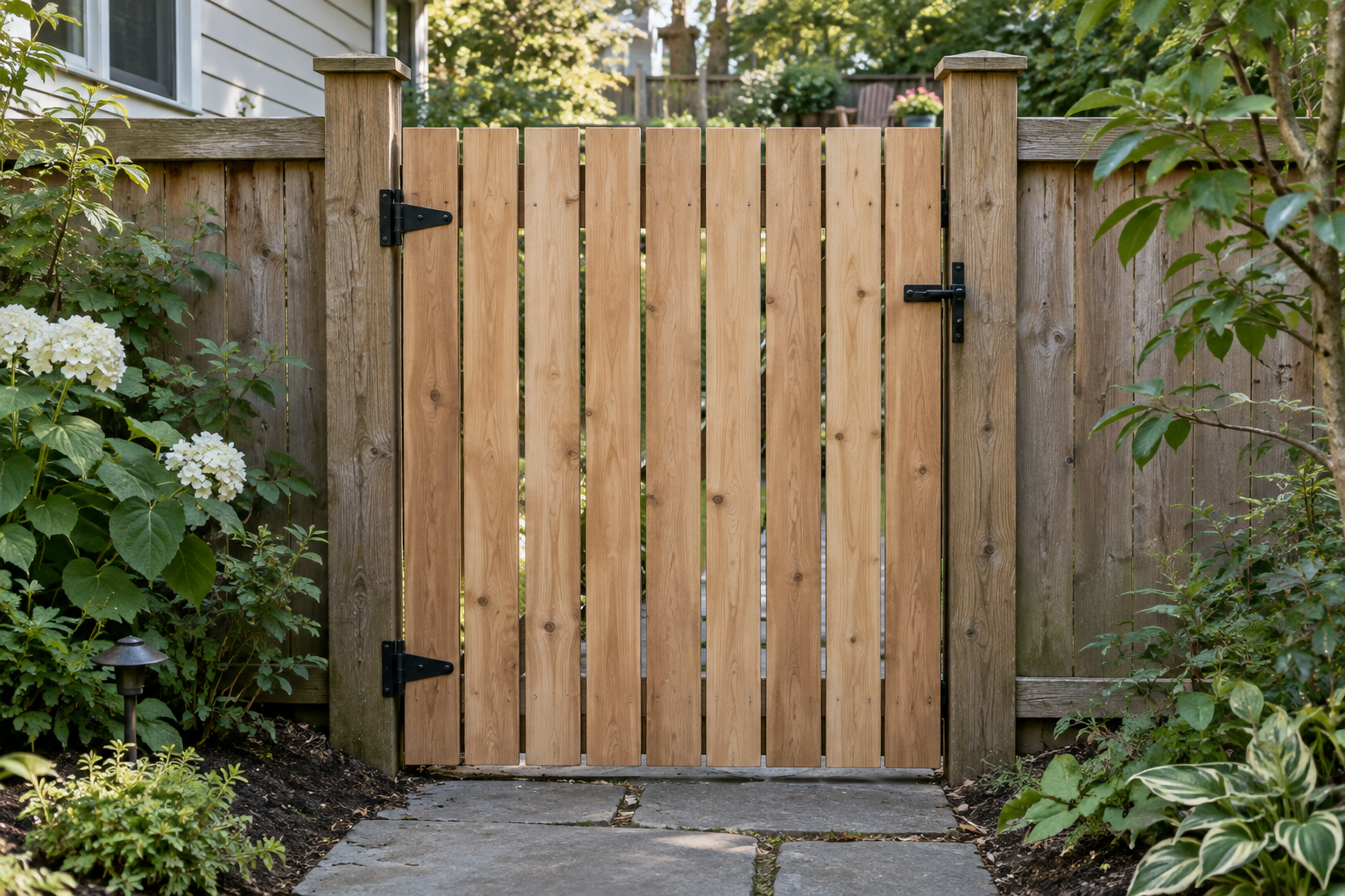
The key rule: a solid wooden compression brace runs from the bottom hinge corner to the top latch corner. A tension cable runs the opposite way. Combine the correct brace with sound joints, suitable hinges and a stable post.
This guide covers a small, manually operated garden gate. It explains the construction sequence and includes a worked frame layout. Wide driveway gates, automated gates and gates serving pools or other safety barriers need their own design and hardware requirements.
Why does a wooden gate sag?
A rectangular frame can change shape without any board becoming shorter. If its corners rotate, the rectangle becomes a parallelogram and the free edge drops. This is called racking. A diagonal restrains that movement, but it cannot keep the whole gate upright if the hinge post is leaning.
| What moves? | What you will notice | What to check first |
|---|---|---|
| The gate frame | The top rail falls towards the latch; corner angles change | Frame diagonals, joints and brace bearing |
| The hinges or their fixings | The leaf lifts with a clunk; hinge plates move against the wood | Loose fasteners, enlarged holes and hinge-pin wear |
| The supporting post | The frame remains square but the entire gate leans | Post plumb, ground-line decay and foundation movement |
| The boards | The gate bows or rubs after wet weather | Moisture movement, clearance and distorted timber |
Gate width also matters. As a simple illustration, a uniformly distributed 20 kg gate with its centre of gravity 0.45 m from the hinge line creates a gravity moment of about 88 N·m: 20 × 9.81 × 0.45. Moving the same weight twice as far from the hinges doubles that moment. This calculation explains the leverage; it is not a hinge or post sizing method and excludes wind and impact.
Which way should a gate brace go?
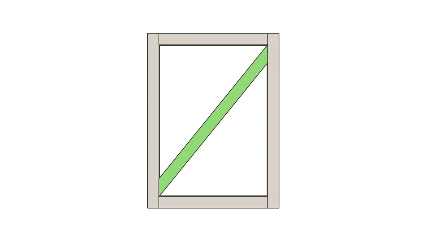
Solid timber: bottom hinge to top latch
Think of the timber diagonal as a prop beneath the unsupported side. As that side tries to fall, it pushes along the brace towards the lower hinge corner. For this arrangement to work, the ends need firm contact with the framing. A decorative diagonal attached only to thin boards does not provide the same bearing path.
Identify the actual hinges before deciding which way is correct. A gate viewed from the other side looks reversed, and a right-hinged gate is the mirror image of a left-hinged gate. The reliable description is always bottom hinge to top latch, rather than “left to right”. [1]
Cable: top hinge to bottom latch
A cable can pull but cannot act as a compression prop. It therefore connects the upper hinge side to the lower latch side. Tightening the turnbuckle draws those corners towards each other. The Onward anti-sag kit instructions show this arrangement and specify supporting the gate before fitting its brackets.
Follow the exact kit instructions for anchors, cable routing and adjustment. Tighten only enough to restore the intended shape; excessive tension can distort a light frame. A cable kit cannot repair rotten wood or stabilise a moving post. [2]
Measure the opening before cutting timber
Choose the hinges and latch first. Their installation clearances affect the finished leaf width, so buying them after making the gate can leave an awkward gap or prevent the gate opening fully.
- Check both posts. Measure the clear opening near the top, middle and bottom. Investigate differences rather than assuming the posts are parallel.
- Mark the hinge line and opening direction. Check walls, fences, handles and latch projections throughout the swing.
- Check the ground through the entire arc. The highest point may be well inside the garden. Allow for planned paving or gravel as well as the current surface.
- Subtract the hardware clearances. Keep hinge-side, latch-side and ground gaps separate in your sketch.
Gate leaf width = clear opening − hinge-side gap − latch-side gap
For a 37 in (93.98 cm) opening, an assumed ½ in (1.27 cm) clearance on each side produces a 36 in (91.44 cm) leaf. This is an arithmetic example, not a universal gap recommendation. Use the chosen hardware’s actual requirements.
The worked frame below has its own dimensions. Measure your opening and calculate the required leaf width before using any example cut list.
For a longer fence run, use the fence planner for the straight fence sections and plan the gate opening separately. A gate leaf is a moving assembly, so ordinary fence-bay spacing does not determine its clearances.
Choose timber and hardware as a system
Start with straight, sound boards. Sight along each piece and reject significant twist, splits at joint locations and loose knots near fixings. A straight frame is much easier to assemble on a flat bench than one that must be forced down with clamps.
Use timber suitable for its exposure. Above-ground framing and a post embedded in soil have different requirements. For treated timber, confirm the use classification and follow the supplier’s instructions for cut-end treatment. For naturally durable species, confirm what you are buying rather than assuming every piece has identical durability.
Wood exchanges moisture with its surroundings, and changes in moisture affect its dimensions and performance. Leave working clearance and follow the timber supplier’s guidance on installation moisture. Finishing the surface does not make timber dimensionally fixed. US Forest Service: moisture relations in wood.
Hinges and fixings
- Choose hinges whose manufacturer permits the gate’s weight, width, thickness and outdoor exposure. A weight number alone does not describe every installation.
- Position hinge straps over substantial framing, with fixings entering sound timber. Thin cladding is not the hinge’s structural support.
- Use the specified fastener type, diameter, embedment and hole pattern. Check whether the rating applies to one hinge or a set.
- Match the corrosion protection of screws, bolts and hinges to the timber treatment and environment. Coastal exposure needs particular attention.
- Include a suitable stop so closing loads are not taken only by the latch mechanism.
Before hanging the gate, the post and its foundation must be suitable for the actual gate and site. Ground conditions, frost, wind exposure and gate width prevent a single post-hole depth from being a dependable answer for every garden.
Tools to have ready
Tape measure, pencil, square, level, clamps, drill/driver, drill bits, a suitable saw, chisel, sanding block and stable work supports. For half-laps, a router or controlled-depth saw cuts can remove most of the waste, with a chisel finishing the joint. Clamp the work and use the tool manufacturer’s guarding and protective-equipment guidance.
Compare cedar and pressure-treated timber before sourcing the frame. Use the outdoor screw guide to check corrosion compatibility and fastener type.
Plans for your next build
Choose a gate design and coordinate it with the surrounding fence.
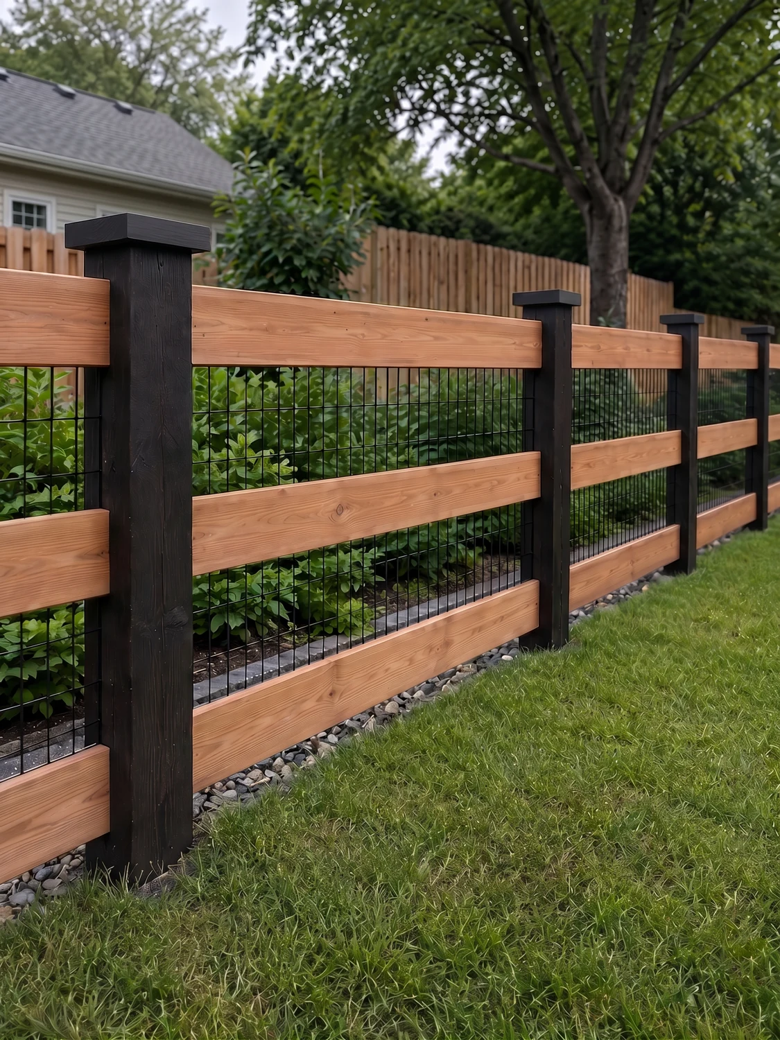
Worked example: a 36 × 48 in (91.44 × 121.92 cm) gate frame
This example uses a rectangular frame with four half-lapped corners, one fitted compression brace and nine vertical spaced boards. The gate is 36 in wide × 48 in high (91.44 × 121.92 cm). All calculations use inches; centimetres are shown alongside for reference. Stock sections are actual finished dimensions, not nominal sizes. Measure your boards before marking joints.
This worked layout illustrates a small gate frame. Select the joint fixings, timber, hinges and post arrangement for the actual gate and exposure before building.
| Part | Qty | Actual section | Length / preparation |
|---|---|---|---|
| Vertical stiles | 2 | 1½ × 3½ in (3.81 × 8.89 cm) | 48 in (121.92 cm); half-lap both ends |
| Top and bottom rails | 2 | 1½ × 3½ in (3.81 × 8.89 cm) | 36 in (91.44 cm); half-lap both ends |
| Compression brace | 1 | 1½ × 3½ in (3.81 × 8.89 cm) | Start with a 56 in (142.24 cm) blank; mark and trim to fit |
| Vertical face boards | 9 | ¾ × 3½ in (1.905 × 8.89 cm) | 48 in (121.92 cm); square-ended in this example |
The listed timber totals 224 linear in (568.96 cm) of 1½ × 3½ in (3.81 × 8.89 cm), including the brace blank, and 432 linear in (1097.28 cm) of ¾ × 3½ in (1.905 × 8.89 cm). Add cutting losses and reject allowance, then lay out the pieces against your supplier’s stock lengths. These totals exclude posts.
Each half-lap is 3½ in (8.89 cm) long and ¾ in (1.905 cm) deep when the stock really measures 1½ × 3½ in (3.81 × 8.89 cm). Measure your boards first. With half-laps, both rails and stiles retain their full outside lengths; a butt-jointed frame needs different rail lengths.
Nine 3½ in (8.89 cm) face boards occupy 31½ in (80.01 cm). Across a 36 in (91.44 cm) leaf, that leaves 4½ in (11.43 cm) for eight internal gaps:
(36 − 9 × 3½) ÷ 8 = 9/16 in per gap (≈ 1.43 cm)
Lay the boards out across the real frame, keep the outside edges flush and distribute the gaps evenly. The calculated spacing describes this layout only. Adjust the number or width of boards if the application needs different openings. The board calculator helps check full-board layouts; it does not assess gate safety or timber movement.
How to build and hang the gate
1. Cut and dry-fit the frame joints
Mark all four members with a reference face and label their positions. Mark the lap length directly from the mating board’s actual width, then mark half the thickness on each joint. Remove material from complementary faces so the assembled frame is flush.
Cut on the waste side of your lines, remove the waste and flatten the recess. The joint should close under normal clamping pressure. If it rocks on a high spot, correct the fit rather than driving in screws to force it flat.
2. Make the frame square and flat
Assemble it on a flat surface and check the outside dimensions. Measure diagonally between matching outer corners in both directions. A true 36 × 48 in (91.44 × 121.92 cm) rectangle has a 60 in (152.4 cm) diagonal. Both measurements should agree; measure the outside frame corners, not the ends of the fitted brace.
Adjust until both diagonals agree, then verify the corners with a square. Also check that the frame is not twisted: equal diagonals on their own do not prove it is flat. Clamp the frame while completing the joints.
Use an exterior-rated adhesive compatible with the timber and its moisture condition, together with appropriate corrosion-resistant mechanical fixings. Follow the adhesive’s preparation, clamping and cure instructions. Predrill where required, keep fixings clear of vulnerable edges and ensure their tips cannot emerge on the other face. Set the fixing pattern before adding boards so it will not clash with the hinges.
3. Fit the wooden compression brace
Keep the frame clamped square. Lay the brace blank across the opening from the lower hinge area to the upper latch area and mark the real contact lines. Transfer those lines around the timber, cut slightly long and refine the fit.
The ends should bear securely against the framing near the corners. Avoid a loose diagonal whose ends stop short, or a fragile pointed end with almost no bearing area. Do not hammer an overlong brace into place: it can push the frame out of square.
Secure the fitted brace so it cannot shift out of plane, using fixings appropriate to the detail. The timber-to-timber contact carries compression; the retaining fixings keep the brace in position. Recheck both diagonals after fitting it.
4. Fit the face boards without introducing twist
Arrange every board before fastening the first one. Check the two outside edges, top alignment and the distribution of the gaps. Clamp temporary straight guides if that makes alignment easier.
Attach each board to the top and bottom rails using exterior fixings suited to the board thickness and species. Predrill near ends, avoid splitting and keep the screw heads flush rather than buried deeply. Check fastener lengths against the combined board and frame thickness. Any additional fixing into the brace must also avoid protruding points.
Keep the gate supported flat throughout. Fastening bowed boards while the frame is balanced on uneven supports can lock distortion into the finished leaf.
5. Protect cut surfaces and fit the hinges
Ease sharp exposed edges, remove splinters and treat cut surfaces where the timber supplier requires it. Apply the chosen exterior finish according to its instructions, including preparation and drying times. Keep glue surfaces free of finish until the joints are assembled.
Mark hinge positions on structural rails or other framing approved for the chosen hinge. Install the specified fixings, keeping the hinge pivots on one straight line. If using through-bolts, provide the specified washers and tighten without crushing the wood.
6. Hang, test and fit the latch last
Support the leaf securely on blocks at its intended height. Use spacers for the side gaps and check plumb. Fix the hinges to the post following the hardware instructions, with a second person supporting the gate where necessary.
Remove the temporary support and test the full opening arc. The gate should remain clear of the ground and adjacent structures without needing to be lifted. Check the post and hinge plates for movement. Correct a fault now rather than positioning the latch to disguise it.
Fit the latch and closing stop only after the gate swings properly under its own weight. Check that the latch engages naturally, that the handle can be reached from the required side, and that fingers are clear of closing pinch points.
How to diagnose a gate that already sags
Support the gate before loosening any hardware. Work through these checks in order so an adjustment does not hide the underlying problem.
| Symptom | Likely explanation | Useful next action |
|---|---|---|
| Post moves when the open gate is gently lifted | Support or foundation movement | Repair or replace the support before adjusting the frame |
| Hinge plate shifts but the post stays still | Loose fixings or damaged fixing holes | Restore a sound fixing detail; do not simply drive a larger screw into decayed wood |
| Post and hinges are stable; frame diagonals differ | Racking at the joints | Support and square the leaf, repair joints, then restore effective bracing |
| Diagonals agree but one corner twists forward | Warp or twist | Inspect distorted members; a diagonal cable may not correct this |
| It rubs mainly after rain | Swelling or moisture-related distortion | Check gaps and timber condition before trimming the leaf |
| It clears when closed but scrapes halfway open | Rising ground or an installation alignment problem | Check ground levels through the swing and the hinge axis |
After adjustment, test the gate open as well as closed. A latch or wheel that props up the free corner can conceal movement that returns as soon as the gate swings away.
Common questions
Will adding a third hinge stop a gate sagging?
It can be appropriate if the hinge manufacturer specifies three hinges for the leaf. It will not make a racked frame square or a loose post stable. More hinges also require accurate alignment to avoid binding.
Does a wooden gate need an X brace?
Not automatically. The single fitted compression brace shown here addresses downward racking of a small gate. An X is another construction arrangement, with an intersection that must be detailed properly; adding crossed boards does not make every frame suitable for a wider opening.
Can I make this example wider?
Do not just lengthen the rails. A wider leaf changes leverage, weight, joint demand and wind exposure. Reassess the entire assembly or consider two narrower leaves. Two leaves also need a properly planned meeting gap, latch and inactive-leaf restraint.
Will a gate wheel solve the problem?
A wheel can form part of a gate designed to use one on a suitable surface. On uneven ground it may lose contact or lift the leaf. Check the underlying frame, hinges and post before adding a wheel as a repair.
How much clearance should I leave beneath a gate?
Enough for the highest surface throughout the swing, the required movement allowance and the application’s containment needs. Check the whole arc before choosing a figure. A gap that works over level paving may not work over a rising gravel path.
Choose a design from The Garden Gate Collection
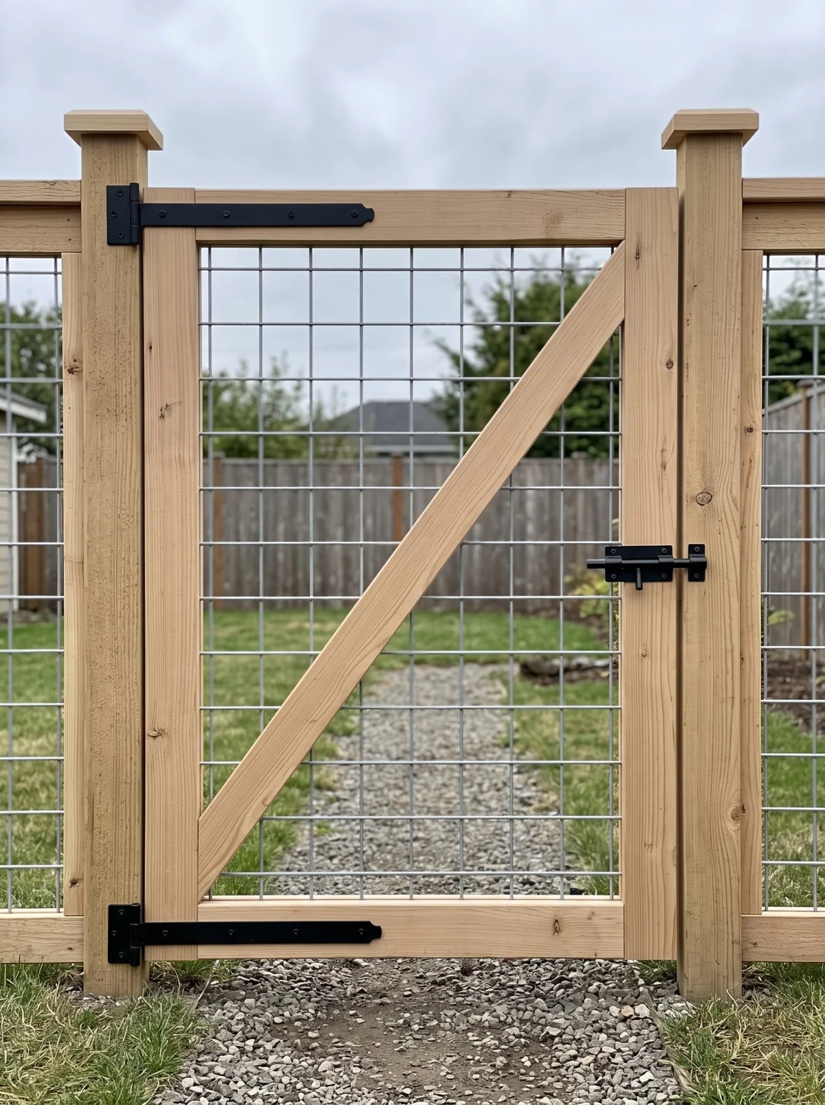
Want a complete design to work from? Our Garden Gate Collection brings together five gate styles, with separate imperial and metric PDF guides, cut lists, hardware guidance, illustrated build steps and SketchUp models.
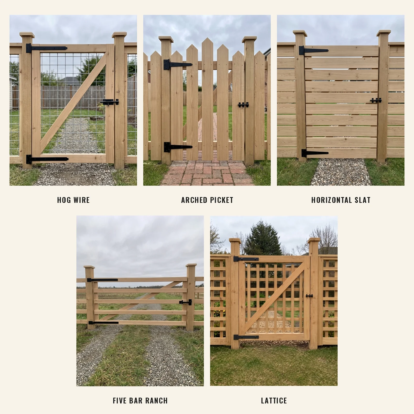
- Hog wire: an open frame with welded mesh and a visible diagonal brace
- Arched picket: pointed boards that rise towards the centre
- Horizontal slat: a taller, near-solid design for more privacy
- Five bar ranch: a wider, open design with its own frame and hardware requirements
- Lattice: a decorative square lattice panel inside a braced frame
The collection uses its own dimensions and joint details. Follow the selected plan’s complete cut list and hardware requirements rather than combining them with the illustrative half-lapped frame above.
A final check before calling it finished
- The post is stable and the hinge pivots align
- The frame is square and flat, with the brace fitted in the correct direction
- All hinge fixings enter sound structural timber
- The gate swings freely with the temporary blocks removed
- The latch engages without lifting the leaf
- Cut ends are treated as required and no sharp fixings protrude
Recheck the gate after the first wet and dry periods and during routine maintenance. Look for loose hardware, changing gaps and water collecting around the post. Reliable operation depends on the complete assembly, not a promise that one diagonal will prevent every future movement.
Plan the rest of the fence
Explore the wood and wire fence project, calculate straight runs with the fence planner, or check board quantities with the board calculator.
For a layout that needs different dimensions or an unusual opening, request custom DIY plans with your measurements, photos and intended use.
Technical references
- Tarmec & Croft: wooden gate bracing direction
- Onward Hardware: 299X-R anti-sag kit installation instructions
- East Coast Fencing: compression bracing, framing and support checks
- US Forest Service, Wood Handbook Chapter 4: moisture relations and physical properties
- Jay Bates: making half-lap joints
Sources checked 21 September 2026. Use the instructions supplied with your actual hardware, timber treatment and finish.