How to cut plywood with a circular saw without splintering
How to cut plywood with a circular saw without splintering
A cleaner plywood cut depends on the blade, face orientation, support and guide position working together
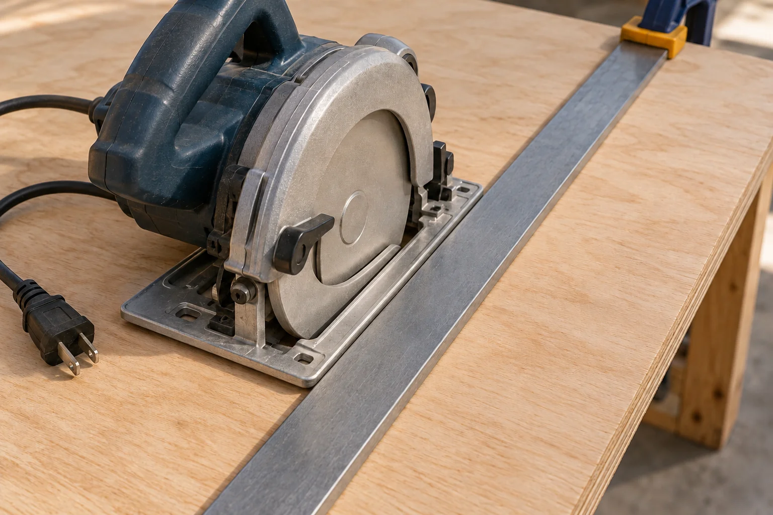
Illustrative imageThe saw is stopped and unplugged
How do you cut plywood with less splintering?
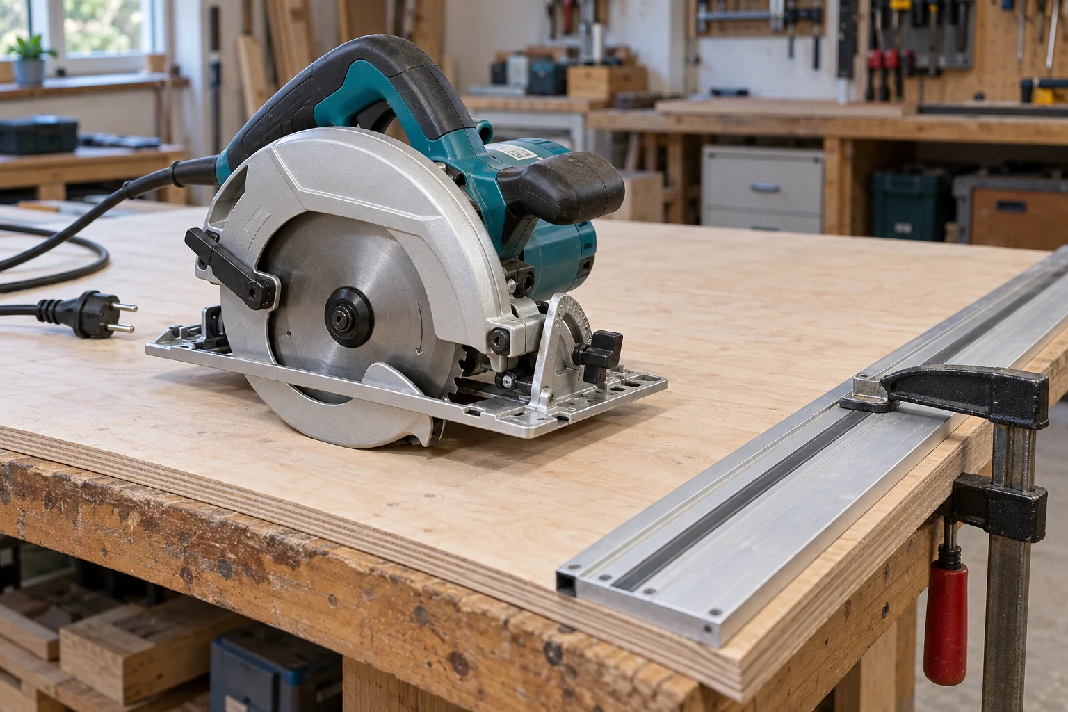
With a conventional handheld circular saw, place the appearance face down, use a compatible sharp blade intended for the panel, support both sides of the cut and secure a straightedge or suitable guide
Make a representative test cut before the project piece, checking the finished width and both faces rather than judging only the top edge
Put the face that matters on the entry side
The teeth enter the underside and exit the top, where tearout is more likely · Blade-path schematic, not a complete operating setup
The teeth of a conventional handheld circular saw enter the sheet from underneath and exit through the upper face, where surface fibres are more liable to break away
Decide which face will be visible in the finished project before marking the sheet, and protect that face from grit or debris on the supports
A track system with splinter-control features may specify a different setup, so use the instructions for that compatible saw-and-rail combination rather than assuming the simple rule applies to every tool
For a shelf, the important face may be underneath at eye level or on both sides; choose it according to the final installation rather than whichever face happens to be uppermost on the bench
Choose the blade for the material and the saw
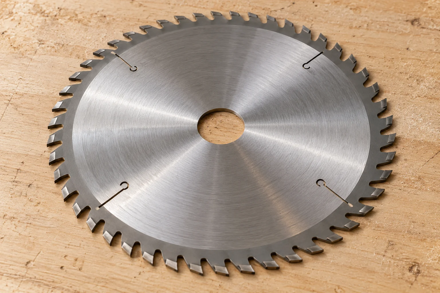
Illustrative imageCheck blade diameter, bore, speed rating and intended material against your saw’s instructions
Start with compatibility, then the intended cut quality; a blade labelled for a fine finish is only an option if it fits the saw’s requirements
Check
Where to find it
Why it matters
Diameter
Saw manual and blade marking
A similar-looking size is not automatically an approved size
Bore or arbour shape and size
Blade specification and mounting requirements
The blade must locate correctly on the saw
Maximum speed and other limits
Blade rating and saw manual
The combination must meet all operating requirements
Intended material
Blade manufacturer’s application list
Plywood, decorative veneers and laminated panels can need different tooth designs
Cut type and finish
Application guidance, not just tooth count
A general construction blade may prioritise a different result from a fine-finish blade
Condition and installation
Physical inspection and fitting instructions
Damage, dull teeth or incorrect installation cannot be corrected by tape on the sheet
For example, Diablo’s D0760A is listed as a 7¼-inch, 60-tooth ultra-finish blade for wood, plywood and melamine; that is a specific material-and-application example, not a recommendation to fit a 60-tooth blade to every saw
Tooth count alone leaves out diameter, tooth geometry and the intended use; a 165 mm blade and a 190 mm blade cannot be treated as interchangeable simply because they have the same number of teeth
A suitable fine-cut blade can improve the edge, but it cannot compensate for a sheet that bends, a guide that moves or a damaged blade
Illustrative image
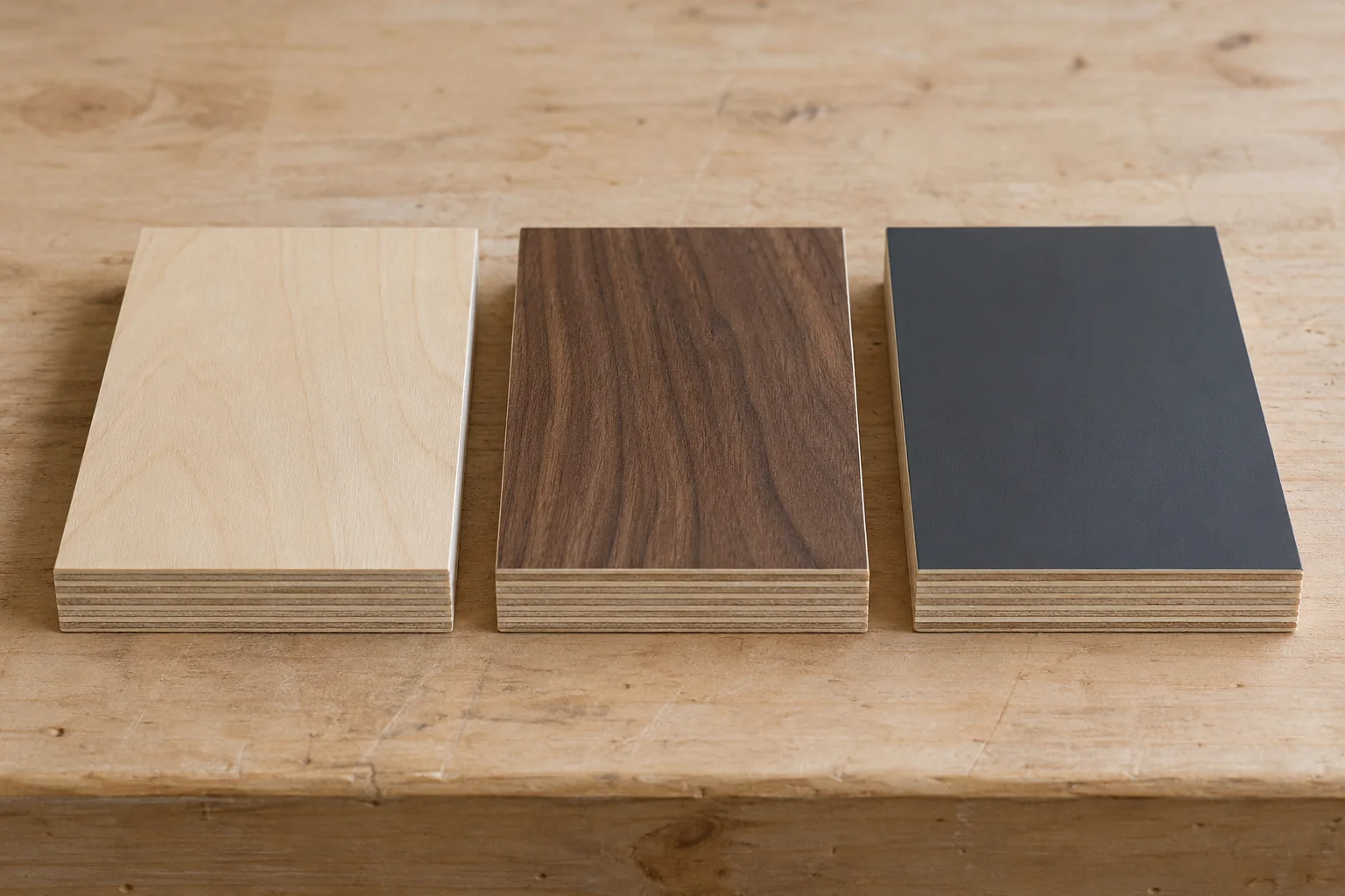
Plain wood faceDecorative veneerLaminate
Identify the actual face material when choosing the blade and setup
Check the face material when buying the blade, especially on decorative or laminated sheets; the plywood core does not describe everything the teeth will cut through
Keep the sheet and the offcut stable
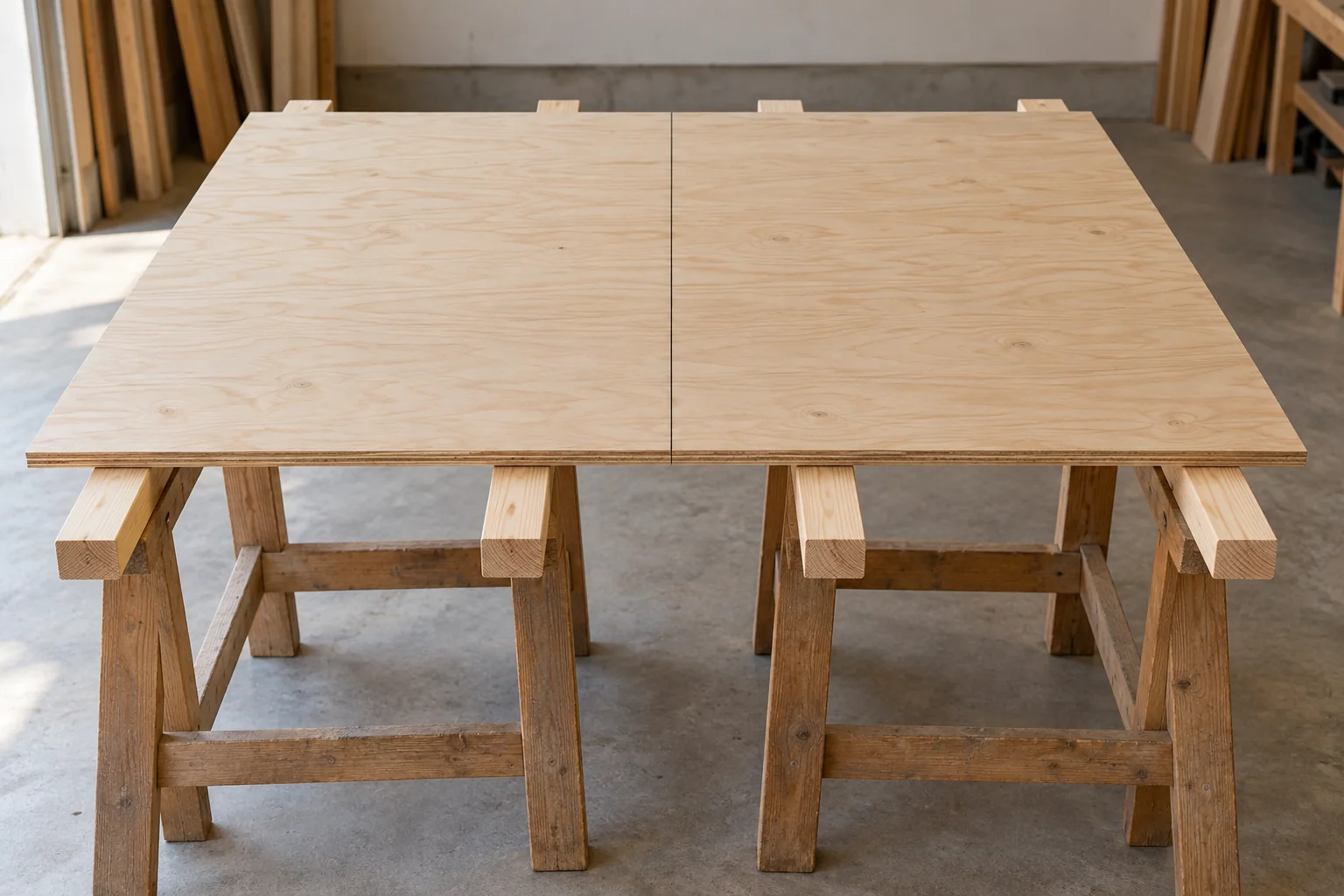
Illustrative imageSupport both sides near the cut and near the outer edges, with clearance below the blade path
Use a stable work platform and support the panel on both sides near the cut and near its outer edges, leaving clearance beneath the blade path
Conceptual top view · Green strips represent support below the sheet, not timber to cut through · Secure the work on a stable platform according to your saw manual
A large unsupported section can sag as the cut progresses; an offcut that drops or moves near the end can spoil the edge and affect control of the saw
Inspect the complete route before powering up: supports, clamps, screws, power cable and extraction hose must not obstruct the saw or blade
Check the underside as well as what is visible from above; a clear pencil line on the face does not mean the blade path below it is clear
Keep the saw base properly supported throughout the intended pass, including entry and exit; do not balance it on a narrow piece simply to make a preferred guide position fit
Allow for the guide offset and the width of the cut
A straightedge guides the edge of the saw’s base, while the blade cuts some distance away; putting the straightedge directly on the finished-size line usually puts the blade in the wrong place
Kerf is the width of material removed by the teeth, which is different from the thickness of the metal blade body
With the saw disconnected, establish the offset for the exact side of the base you will run against the guide; measure to the blade’s cutting edge on the kept-piece side and confirm the effective offset with a test cut
Worked example: a 400 mm-wide panel
Assume the guide sits on the piece you are keeping, your verified guide-to-kept-edge offset is 120 mm, and the blade removes a 3 mm kerf
Finished width: 400 mm Guide contact edge: 400 − 120 = 280 mm from the reference edge Blade removes material from 400 to 403 mm on the waste side
Illustrative top view, not to scale · The guide’s contact edge is 280 mm from the left reference edge · The entire kerf belongs on the waste side
Mark the finished width from one sound reference edge at both ends, set the guide contact edge at the calculated position and confirm the finished width on matching scrap
The 120 mm offset and 3 mm kerf are example values, not settings for your saw; a different blade, base side, bevel or guide arrangement requires checking again
If the guide is placed on the opposite side, do not reuse the subtraction blindly; lay out the relationship between its contact edge and the required cutting edge for that setup
Why kerf matters when dividing a sheet
A 600 mm-wide piece split once with a 3 mm kerf cannot produce two 300 mm pieces; equal finished pieces would each be (600 − 3) ÷ 2 = 298.5 mm
Allow for each planned cut when laying out a cut list, and check whether any stated project dimensions already include a machining allowance
Set up, test and make the cut
Disconnect power before adjustments
Unplug the saw or remove its battery before adjusting the setup or changing the blade; check the guard and use the eye, hearing and dust protection specified for the work
Set the cutting depth
Use the projection required by your saw manual for the sheet thickness; Bosch’s linked circular-saw instructions specify less than a full tooth visible beneath the material, rather than maximum blade depth
Secure the depth and bevel adjustments before the test
Position the guide
Allow for the verified base offset and put the kerf on the waste side of the finished dimension
Clamp the guide securely and check clearance along the full route while the saw is disconnected
Illustrative imagePosition the guide for the offset between the blade and the guide edge of the saw base
Try matching scrap
Use the same blade, face orientation and guide arrangement; test the relevant cut direction through the same type of panel
Measure the finished width at both ends and inspect both faces, noting whether any damage occurs along the whole edge or mainly at the exit
Change one setup variable at a time so that an improved result tells you something useful
Cut in the normal forward direction
Use the grip, starting procedure and controlled feed specified for the saw; let the tool follow the guide without forcing it sideways
If the blade binds, release the trigger and hold the saw still until it stops before investigating; never pull a running blade backwards through the cut
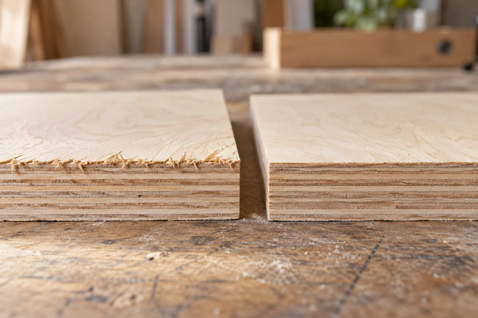
Illustrative imageSurface-veneer tearout compared with a cleaner edge
When both faces need a clean edge
Test both faces on matching scrap; putting the appearance face down alone does not guarantee two clean edges
Bosch’s PKS guide documentation describes a rubber splinter-control lip trimmed to the saw on its first pass; a plain straightedge controls direction without providing the same surface support
Check whether the system protects the kept piece, the offcut or both; if the sample is unsuitable, improve the setup or use a suitable cutting service before cutting the final size
Does masking tape prevent tearout?
Panel guidance describes tape as an aid for some faced materials, not a guarantee; test its adhesion and removal on the actual surface first
Should I score the line?
Use scoring only where appropriate to the panel and tool, keeping the final kerf on the waste side
Do not improvise a backwards scoring pass with a conventional circular saw
If the edge still splinters
Result
What to inspect
What the next test should establish
Upper face chips along the cut
Face orientation, blade application and available splinter protection
Whether the appearance face meets the finish requirement
Damage appears mainly at the end
Sheet and offcut support at the exit
Whether movement as the cut finishes is causing the defect
Width is wrong by a consistent amount
Reference edge, guide offset and which side contains the kerf
Whether the setup produces the intended finished dimension
Width changes from one end to the other
Guide alignment, guide movement and base contact
Whether the cut is parallel to the chosen reference
Cut wanders, binds or burns
Blade condition, alignment, support and the specified feed method
Resolve the cause before continuing on the project piece
Only one face is acceptable
The side protected by the cutting system
Whether both required faces can meet the finish standard
Keep a sample with the blade and setup recorded; it gives you a physical reference for the next sheet, while still requiring a new check if the panel or blade changes
The offset diagram and arithmetic are illustrative and use a 120 mm offset with a 3 mm kerf · Your saw and guide instructions determine the actual setup